
Gravity separation is the main way for separation of manganese oxide ore. The manganese gravity separation flow chart is showed in the following picture: After two crushing, most of manganese granules have been liberated from the other
 WhatsAppGet PriceGet A Quote
The permitted production limits are 1.60 MTPA of Iron Ore and 0.2614 MTPA of Manganese ore. Manganese Ore occurs in pockets and pods with a size range of few metres to about 40
WhatsAppGet PriceGet A Quote
725;4.7 Hydrometallurgical Process Flow-Chart. The flow chart summarizing the important analytical operations for the recovery, purification and beneficiation of a Nigerian
WhatsAppGet PriceGet A Quote
Electrolytic Manganese Dioxide (EMD) | Mesa Minerals Limited. Overview. The first step in a conventional production flow sheet for converting manganese oxide ore to alkaline grade
WhatsAppGet PriceGet A Quote
1219;The flowchart of processing fine manganese ores in the jet-emulsion unit is shown in Fig. 1.Furnace charge materials, such as manganese concentrate, coal, pulverized
WhatsAppGet PriceGet A Quote
86;The process flow of the manganese ore processing plant is based on the results obtained from laboratory ore dressing tests and industry tests. The magnetic separation
WhatsAppGet PriceGet A Quote
6 ;This setup is a 1500 tpd rock manganese ore process plant, it is configured by a feeding crushing system, grinding system, and 3-stage gravity separation system.. The crushing system is 150 tph capacity, 10 working
WhatsAppGet PriceGet A Quote
The process flow diagram for the electrolytic production of manganese includes seven process stages: Leaching Ore or Concentrate with Sulfuric Acid After crushing to a fraction of 0-20 mm
WhatsAppGet PriceGet A Quote
Oxide manganese usually adopts washing and gravity separation solutions for beneficiation. Weathering-type manganese oxide ore often contains a large amount of mud and powder ore,
WhatsAppGet PriceGet A Quote
113;This setup is for the manganese ore process:raw bin+vibration feeder, jaw crusher, belt conveyor, cone crusher, belt conveyor, vibration screen, belt conveyo...
WhatsAppGet PriceGet A Quote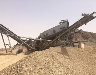
330;Manganese sulfate is an important base manganese salt; nearly 80% of the world''s manganese products are produced using manganese sulfate or manganese sulfate solution.
WhatsAppGet PriceGet A Quote
Download scientific diagram | Schematic flow diagram of the leaching and separation of manganese sulfate from pyrolusite ore. from publication: Recovery of pure MnSO 4∙H 2O by
WhatsAppGet PriceGet A Quote
202449;Adding manganese to steel improves its deformability, producing complex shapes and parts without material cracking or breaking. Adding manganese to cast iron when processing it into steel helps remove the sulfur
WhatsAppGet PriceGet A Quote
process flow chart manufacturing process zones of a silico-manganese furnace crushing and grinding of the ore: concentration or beneficiation of the ore: magnetic separation of impurities:
WhatsAppGet PriceGet A Quote
201638;The Mineral Processing Flowsheets shown on the following pages are based on actual data obtained from successful operating plants. Metallurgical data are shown in these
WhatsAppGet PriceGet A Quote
The process flow diagram for the electrolytic production of manganese includes seven process stages: Leaching Ore or Concentrate with Sulfuric Acid After crushing to a fraction of 0-20 mm
WhatsAppGet PriceGet A Quote
410;Next, I will introduce the detailed manganese ore processing production line to you. 1. Manganese ore crushing process and equipment Manganese ore crushing is the first step in the process, which involves
WhatsAppGet PriceGet A Quote
1219;The flowchart of processing fine manganese ores in the jet-emulsion unit is shown in Fig. 1.Furnace charge materials, such as manganese concentrate, coal, pulverized
WhatsAppGet PriceGet A Quote
202031;The original supply in the manganese flow is composed of manganese from ore and scrap. Ore included manganese and iron ore, from which iron is principally recovered, but
WhatsAppGet PriceGet A Quote
With manageable sized ore in-hand, the rest of the ore processing steps are determined by the ore type. Ore processing flow sheets spell out the most appropriate processing method for
WhatsAppGet PriceGet A Quote
A customer is interested in a jigging plant of about 10 tph to process manganese ore. They think the material is pyrolusite with silica inclusions. 1. Raw materials: Manganese Ore(pyrolusite
WhatsAppGet PriceGet A Quote
201638;The Mineral Processing Flowsheets shown on the following pages are based on actual data obtained from successful operating plants. Metallurgical data are shown in these flowsheets which incorporate Crushers,
WhatsAppGet PriceGet A Quote
410;Process flow: Vibrating feeder → jaw crusher → hydraulic cone crusher → vibrating screen. The raw manganese ore (≤350 mm) is transported to the silo by the loading
WhatsAppGet PriceGet A Quote
2019729;Significant variability in ore grades and mineralogical characteristics impose challenges during selection of a proper beneficiation process to upgrade the low-grade
WhatsAppGet PriceGet A Quote
2016311;911 Metallurgist is a trusted resource for practical insights, solutions, and support in mineral processing engineering, helping industry professionals succeed with proven
WhatsAppGet PriceGet A Quote
621;The flow chart shows the basic steps of how iron ore is used to produce semi-finished products of steel. The individual process steps are explained in more detail in the following articles. Figure: From iron ore to steel
WhatsAppGet PriceGet A Quote
process flow chart manufacturing process zones of a silico-manganese furnace crushing and grinding of the ore: concentration or beneficiation of the ore: magnetic separation of impurities:
WhatsAppGet PriceGet A Quote
When iron ore is extracted from a mine, it must undergo several processing stages. Six steps to process iron ore. 1. Screening We recommend that you begin by screening the iron ore to
WhatsAppGet PriceGet A Quote
20241226;Understanding the nickel processing flow chart is essential for industries to optimize extraction and refining methods. +86 18234403483 [email protected]
WhatsAppGet PriceGet A Quote
of Manganese Ore. • Screening: The material is screened so that uniform sizes are obtained for further process. • Zigging: Water jigging is done to separate and wash impurities. •
WhatsAppGet PriceGet A Quote
 WhatsAPP 24h online service


 24h Online Chat


